Fundamental to various devices and systems, oscillators are components that produce repetitive,...
Additive phase noise refers to the phase noise introduced by subsystems or specific components within a signal chain, characterizing devices or systems that signals pass through, rather than those that generate a waveform natively. Components targeted for this type of analysis include mixers, amplifiers, and other multi-port signal processing devices. In this blog post, learn how to properly configure your hardware setup to measure the additive phase noise of a device under test (DUT).
Hardware Configuration for an Additive Measurement
In a typical setup for additive measurements, a signal source is used to drive the process. This signal is split into three distinct paths:
- Path 1: A portion of the signal passes through the DUT. This path will be used to understand the DUT’s impact on signal quality, observing how much phase noise it adds to the signal.
- Paths 2 and 3: These two paths are derived from the same signal source as the DUT but are not affected by the DUT’s phase noise. They first pass through phase shifters, which are used to offset the phase 90 degrees (or in quadrature) from path 1. A quadrature alignment enhances sensitivity and accuracy, distinguishing DUT phase deviation more clearly during analysis. Next, the two paths feed through the front panel of the phase noise analyzer via the LO input ports. Traveling down two independent channels, paths 2 and 3 provide the necessary reference signals for accurate path 1 comparison.
Cross correlation is used to isolate the DUT’s phase noise from other noise sources, such as contributions from the measurement setup. For example, a signal source or generator serving as the LO introduces phase noise common to all signal paths but is not the target for analysis. Cross correlating the different signal paths can uncover and remove these common noise contributions and reveal the specific DUT phase noise that is of interest.

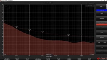
Additive Phase Noise Measurement Example
The video, “How to Make an Additive Phase Noise Measurement with the HA7062 Series Phase Noise Analyzer,” provides a step-by-step guide through setting up the instrument hardware and navigating the graphical user interface (GUI) for an additive phase noise measurement.
Key Maury Microwave components of the Holzworth product line featured in the example setup include:
Phase noise analyzer: The HA7062D phase noise analyzer is used to evaluate the phase noise performance of the DUT, offering outstanding accuracy, very high reliability, extremely fast measurement speed, and the ultimate configurability.
DUT: Serving as the DUT, the HX2600 broadband, ultra-low phase noise RF amplifier is designed for use as a pre-amplifier for phase noise measurements of devices with low output power.
Phase shifters: The two reference paths use HX5100 Series electronic phase shifters, which are frequency-specific and allow for full automation of additive/residual phase noise measurements with the Holzworth test systems while maintaining the ANSI z540 calibration.

Take a look at the example test setup in action in the video below. In addition to reviewing the hardware configuration, viewers will learn how to traverse the GUI to measure the additive phase noise of a DUT. Connecting the instrument to the GUI, setting up measurement parameters and desired correlations, powering the amplifier, and configuring the phase shifters — this video is a must-watch tutorial for additive phase noise analysis.